|
|
|
|
|
|
| Home | Company Info | Blog | Tutorials & Tools | Forums | Store | Services | Contact | Site Map |
Designer Tutorial 1 |
Microstrip Transmission LineDesignerv3.5 (download simulation file) Ansoft Designer is a microwave engineering CAD suite that allows for circuit and full-wave simulation. In this tutorial, a microstrip transmission line is simulated with Designer. The basic model of a microstrip transmission line is shown in Fig. 1. The microstrip line will be designed on a substrate with a dielectric constant of 10.2 and a height of 1.27 mm at 5.0 GHz; the width of the microstrip is designed for 50 Ω and the length for a 180 degree phase delay. 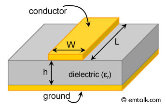
Figure 1. Model of microstrip line showing cross-section (transverse to propagation). The methods used to setup the simulation are outlined. In particular, the following topics are covered:
Planar EM Design Setup in DesignerFirst load up Ansoft Designer, then go to Project > Insert Planar EM Design to launch the MOM simulator. A window will appear asking you to choose a layout technology (substrate) as shown in Fig. 2. Pick MS - RT_duroid 6010 with a height of 0.010 inch. Once, you have chosen the technology, a project window will appear. Before we can setup the model, we need to correct the substrate height. To do this, go to Layout > Layouts and the Edit Layers window will appear as shown in Fig. 3. Change the thickness of the dielectric to 1.27 mm and the trace to 0 mm. If you like to save the substrate for future use, click on File > Save As Technology File and next time you insert a new planar EM design, you can select the same substrate. 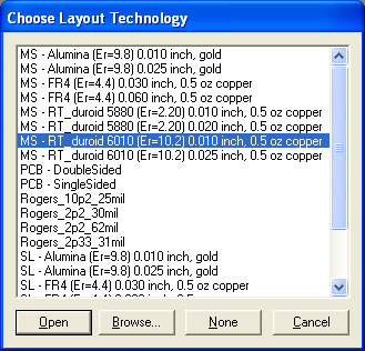
Figure 2. Choose layout technology window. 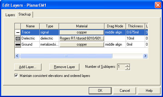
Figure 3. Layers dialog box. Model SetupYou are now ready to draw the microstrip line trace. Before doing so, the width and length have to be determined. Using the microstrip line calculator, a width of 1.19 mm and a length of 11.47 mm is needed to realize a 50 Ω with a 180 degree phase delay at 5.0 GHz. To draw the trace, click on the rectangle tool or go to Draw > Primitive > Rectangle. Just draw any size rectangle for now. After it is drawn, double-click on it and the dialog box will appear; fill in with the values shown in Fig. 4. Save the project before continuing if you have not already done so. 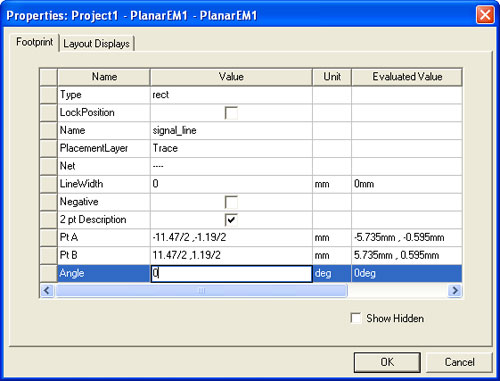
Figure 4. Rectangle dialog box. Excitation SetupThe excitation ports for the microstrip line have to be setup. To do this, go to Edit > Select Edge and select the left edge of the microstrip line. Then assign a port by clicking on Draw > EdgePort. Do the same for the right edge. Make sure to make the ports Edge Ports and not Gap Sources, by going to Planar EM > Port Excitations and unchecking the Gap Source box. The completed microstrip line model should look like Fig. 5. 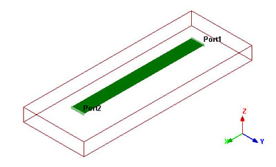
Figure 5. 3-D view of completed microstrip transmission line drawn in Ansoft Designer. Analysis SetupTo setup the analysis, go to Planar EM > Solution Setup > Add Solution Setup. Since this is a geometrically simple structure, a fixed mesh will give an accurate result. Use a fixed mesh with a frequency of 10.0 GHz. In addition, add a frequency sweep from 2.0 GHz to 8.0 GHz by going to Planar EM > Solution Setup > Add Frequency Sweep; do an interpolating sweep from 2.0 GHz to 8.0 GHz with 201 points. Next, analyze the problem. Plotting ResultsAfter the simulation is finish, we can confirm that the characteristic impedance is 50.345 Ω and has a S21 phase of 176 degrees by going to Planar EM > Results > View Profile and looking at the matrix data at 5.0 GHz. Fig. 6 shows the profile window with matrix data at 5.0 GHz. 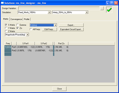
Figure 6. Matrix data dialog box. Next, a S-parameter magnitude plot is created showing the return and insertion loss of the microstrip line by Planar EM > Results > Create Report and plotting S11 and S21. The resulting plot is shown in Fig. 7 which shows the microstrip line is broadband. 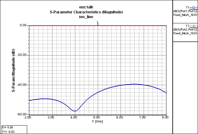
Figure 7. Numerical return and insertion loss. Discuss this in the forums. |
|
em: talk � 2006-2009 | All Rights Reserved | Privacy Policy |
|